


.JPG)


 Actually this stuff is made for a Simple(labs) competition. Problem statement is to indicate the power loss by blinking an LED after the power goes off. We thought of storing the charge in capacitor, like everyone. It seem simple at first, complex then, finally pretty easy.
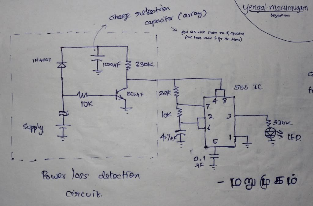
Operation is simple. When power is available the Capacitor is charged through the PN Junction Diode(1N4007). The transistor is kept ON by the power supply. When the power goes OFF, the Capacitor drives the 555 timer - Blinking Circuitry to indicate that the power is lost. Click here to see 555 timer Basics
Here is the circuit.
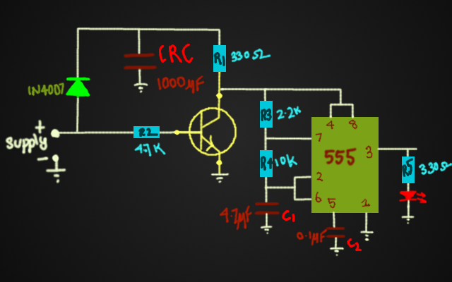
Operation Simplified....
Downloads: Files Video


