Sunday, 8 April 2012

Guides : Basics Of Programming

     I had an intention to write a book just after completing my higher secondary to help students, and make them learn thing easily. But at that time, with very little experience in writing articles, how could I write a book. Also I didn't have expertise in any field. But the idea writing a book for C-programming strike long ago in the beginning of 2010. But I came to know that there are much better books available in internet, why should I write one.

Book Cover

    After completing the fourth semester, I realized that pupil still do not have enough experience with C-programming. I started writing this guide, with a title of "Programming in C for Embedded System". I have asked my fellow students about this, but the questions they asked me narrowed my research. I started rephrasing them into Basic constructs Programming text. It took nearly two weeks to finish with my so called record works. I thought I could publish this guide before a week. Unfortunately I was unable to complete the text. And finally, here it is.

      Section 01: Variables and Arrays
      Section 02: Execution and Control Flow
      Section 03: Functions

    Say something in comments sections.

Friday, 3 February 2012

Power Loss Indication

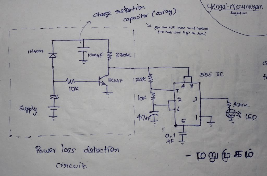
    Actually this stuff is made for a Simple(labs) competition. Problem statement is to indicate the power loss by blinking an LED after the power goes off. We thought of storing the charge in capacitor, like everyone. It seem simple at first, complex then, finally pretty easy.

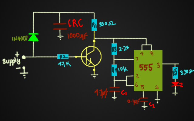
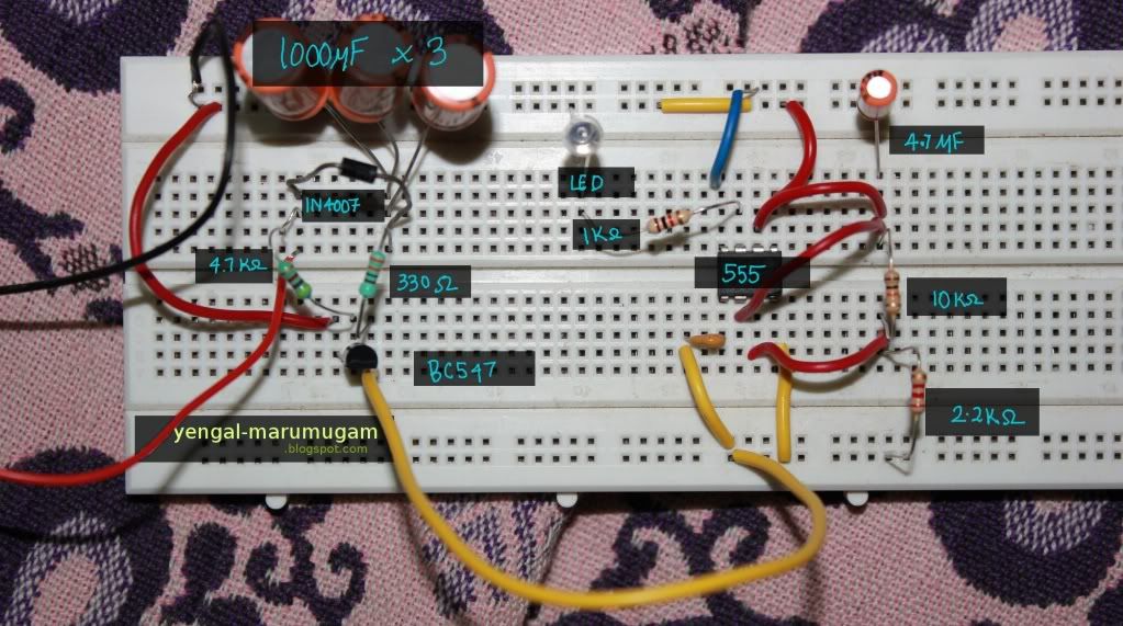
    Operation is simple. When power is available the Capacitor is charged through the PN Junction Diode(1N4007). The transistor is kept ON by the power supply. When the power goes OFF, the Capacitor drives the 555 timer - Blinking Circuitry to indicate that the power is lost. Click here to see 555 timer Basics

Here is the circuit.

Operation Simplified....

   Actually the 555 timer circuitry operates in Astable Mutlivibrator Mode to generate a pulse. The pulse is used to drive the LED - On/Off. The supply to the 555 is supplied by the Charge Retention Capacitor (array). It is nothing but a ordinary capacitor of high capacitance value. Diode is used to prevent the transistor to be biased from capacitor. The transistor goes Off with the power, so the charge from Capacitor is used to run 555 timer circuitry.


Downloads:  Files    Video

Sunday, 4 December 2011

Interfacing PS2 Controller with Arduino

    In the previous post PS2 Controller Outline, the pin configuration, specifications and working of different buttons of PS2 controller are explained. In this post we interface the controller with an Arduino development board and test a sample program. We seperate this into two sections; the hardware and software sections. The hardware section is pretty much straight forward which involves connecting controller wires to arduino pins. In the software section, we use the PS2X class in "PS2 controller Arduino Library v1.4" provided by billporter.

Hardware Section:

    Out of 9 wires from the PS2 controller, we here use only 6 pins. They are Vcc(red), gnd(black), clock(blue), command(orange), attention(yellow), data(brown).


PS2 Controller Pins Arduino Pins
Vcc 3V3 pin of on-board FTDI chip
gnd digital ground pin
*clock pin 13
*command pin 11
*attention pin 10
**data pin 12


    * Note1: clk, cmd, att, data can be connected to any of the digital pins and program can be modified accordingly.

  ** Note2: The data pin should be connected as shown in the figure

Software Section: 
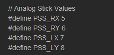
    The library is available for download at billporter. In the PS2X class, all the button states are defined as constants as given below:


Some of the important functions defined are given below:

1. config_gamepad(clock,command,attention,data,Pressures?,Rumble?)
                 This function configures the PS2 controller and returns a corresponding result in byte format. The pins to which clk, cmd, att and data are connected should be entered in this function for initial setup. Pressure and Rumble are boolean values which can be enabled or disabled.

2. read_gamepad()
                This function is called to get new values from the controller. This should be called atleast once in a second. It can also be used to set vibration strength of the vibrating motor.

3. Button(Button_Constant)
                This function returns a boolean value depending on whether a button is pressed or not. It takes a button constant as argument.

4. Analog(Button_Constant)
                This function takes Button_Constant as argument and returns a byte which represents the analog value of the button (ie) the position in case of stick and the pressure with which the button is pressed in case of pressure button.

5. ButtonPressed(Button_Constant)
                It returns a boolean value based on whether a button is just pressed or not.

6. ButtonReleased(Button_Constant)
               It returns a boolean value based on whether a button is just released or not.


7. NewButtonState(Button_constant)
                             It returns a boolean value based on change in button state.


Sample Code:
    Having discussed the software and hardware sections, lets now examine the example code given in the library itself. Click here to view the sketch "PS2X_Example".


ALGORITHM:
  • Include PS2X_lib.h
  • Create an instance for PS2X class

SETUP:

  • Set baud rate
  • Configure the game pad
  • Identify the controller type 
  • Display results in Serial Monitor

LOOP:

  • Read game pad ( read_gamepad( ) )
  • Check all the button states 
  • If any button is pressed, display it in serial monitor
  • If L1 or R1 is pressed, display the analog stick values in serial monitor
  • Call a delay of 50 milliseconds.
Screenshot of serial monitor:


Monday, 24 October 2011

SRAM Data memory and Stack Pointer

SRAM data memory:

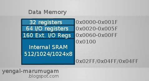
     The data memory is divided into 32 locations for register file, next 64 locations for standard I/O memory, 160 locations for extended I/O memory and the next 1024 (* 1K memory for atmega168) locations for internal data SRAM. (* Internal data memory varies for atmega48/88/168/328 as 512,1K,1K,2K respectively).

   The data memory map of AVR is given in the figure.

Register File:
     A Register file is an array of registers in a CPU. This serves as the central architectural element of any AVR uC. Each register is implemented by using SRAM (static RAM) with dedicated ports for reading and writing. In AVR, the register file is optimized for enhanced RISC (reduced instruction set computing) architecture with single clock cycle access time, which means 2 operands are accessed from 2 registers, the operated is executed and the result is stored in a register in one clock cycle.

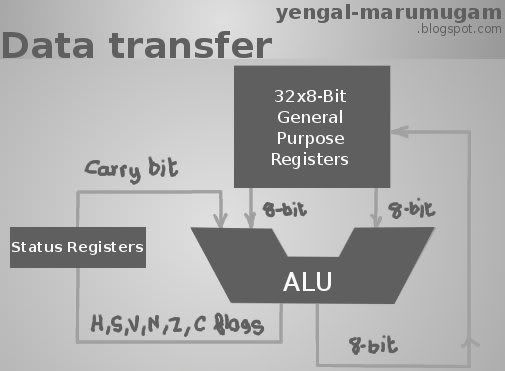
Data Transfer between General Purpose Registers and ALU


      The general purpose register file is classified into 32 8-bit registers, namely r0 to r31. Although the register file of AVR is normally perceived as a 32x8 bit storage unit, it is actually a 16x16 unit. This format is necessary for updating 16bit (26 to 31) memory pointers in a single cycle. These memory pointers (ie) 26-27, 28-29, 30-31 pairs serve as 16bit address pointers for indirect addressing of data, named X, Y and Z pointers respectively. These address registers have some special functions like fixed displacement, auto increment and auto decrement. The addressing (00H - 1FH) of each register is given in the following table:


16 x 16 bit array addresses
Address 15-8 (high) 7-0 (low)
00H r1 r0
02H r3 r2
04H r5 r4
06H r7 r6
08H r9 r8
0AH r11 r10
0CH r13 r12
0EH r15 r14
10H r17 r16
12H r19 r18
14H r21 r20
16H r23 r22
18H r25 r24
1AH r27 r26
1CH r29 r28
1EH r31 r30

I/O Memory:
     The CPU consists of several peripherals namely interrupt unit, SPI (Serial Peripheral Interface) unit, control register, Watchdog timer, Analog comparator, I/O modules, etc. The I/O memory contains the addresses of the basic CPU peripheral functions and other I/O functions. The function of each I/O memory location is fixed by the designer. It consists of 64 memory locations called as standard I/O memory. 

Extended I/O Memory:
     Complex microcontrollers like ATmega48/88/68/328 with more ports and peripheral units cannot be supported within the 64 memory locations. Those extra ports and peripherals are supported by the extended I/O memory which contains 160 memory locations( ATmega48/88/68/328 ). The size of extended I/O memory depends on the micro-controller. 

Internal SRAM:
     The Internal SRAM is the general purpose RAM used by the programmer for storing the intermediate values and results. Hence, it is also known as Scratch-pad. They can be accessed directly by using their address and indirectly by pointers (storing their address in register pairs). The memory locations can be accessed sequentially by use of X,Y,Z pointers (which support auto-increment,-decrement). The size of internal SRAM depends on the micro-controller ( discussed in data memory ).

Stack Pointer :
     The Stack is used for storing temporary data, local variables and return addresses after subroutine calls. The stack pointer points to top most memory location of the stack. The stack advances from higher memory location to lower memory location. It is implemented using 2 8-bit registers in I/O space. 


Reference:

  1.  web.alfredstate.edu
  2.  www.atmel.com

Share

Twitter Delicious Facebook Digg Stumbleupon Favorites More