


.JPG)


I was on hunting of resources on fundamentals of CPU. Energy exhausted. Everything I found was incomplete, irrelevant. Yeah, Internet gives us clues to solve a puzzle. I think I almost solved it.
Consider any process has to be controlled. Who is to control? CPU is the controlling element of any process. This word appeared for the first time during 1960's in the Industries. In late 1960's microprocessor based CPU's came to rule the industries. The microprocessors require many external components for their operation. This increased the cost of project. So, the manufacturers came up with an idea of integrating the minimal external components inside it, necessary for its operation. As the area of application varies the manufacturer introduced a new device, that has many of the important accessories required by wide range of applications. Its is how our micro-controllers were born.
Microcontroller:
Advanced Control Units are designed as Finite State Machines. They work based on the current state they present. It out of scope of this article.
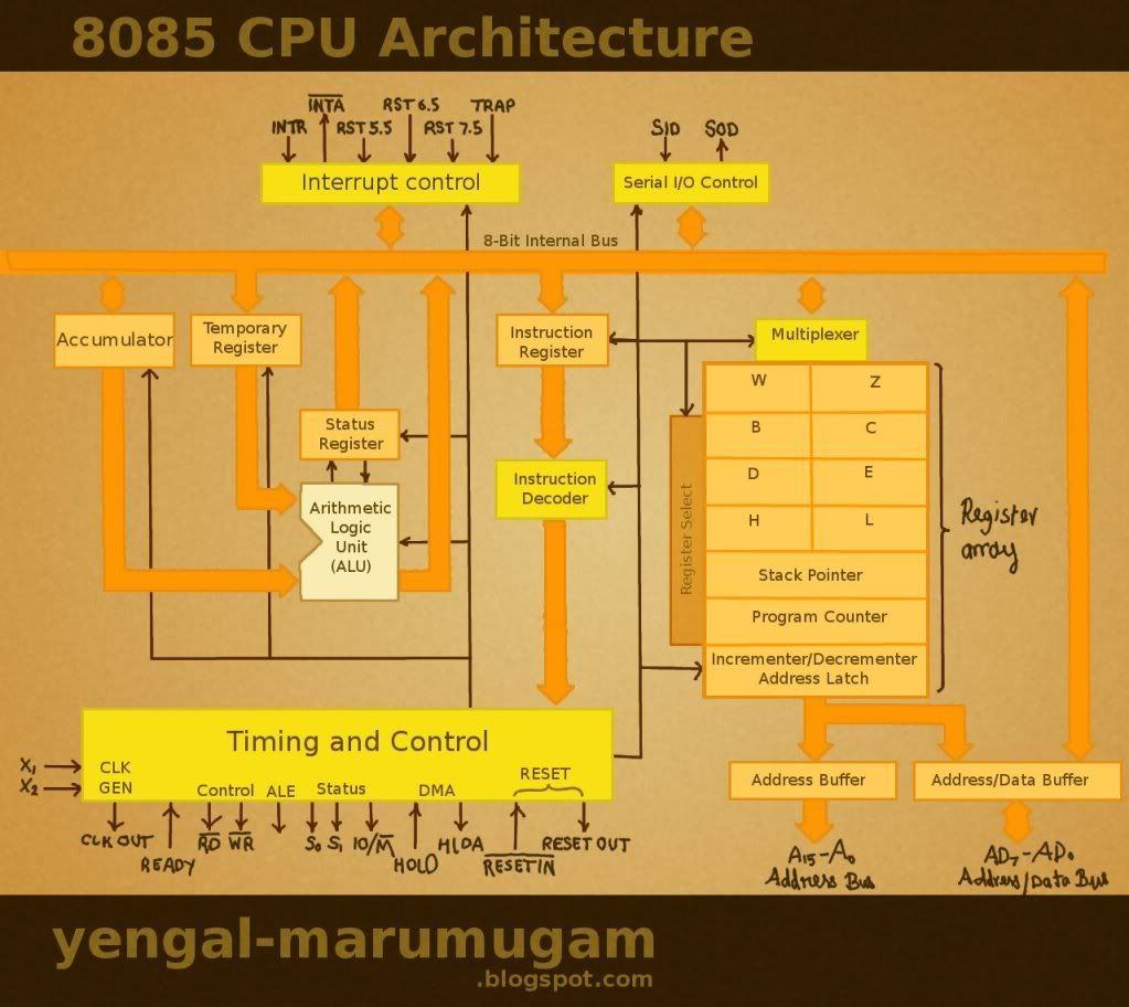
Other that ALU and CU, CPU consists of Register Bank/File, Status Register, Stack pointer. It is a series of 8-bit registers in 8-bit uC and 16-bit registers in 16-bit uC. These are called general purpose registers. Atmega168 contains 32x8-bit registers. 8085 CPU contains 6x8-bit registers. Status register has 8-bits of information about the previous arithmetic-logic operation.
 8-Bit ALU:
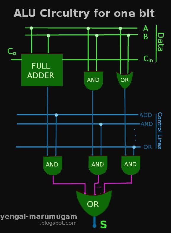
The figure on the left shows the circuit for one bit operation. It is called One-bit Slice.
The ALU consists of different section for different operations. These section can be enabled with proper control codes(lines).
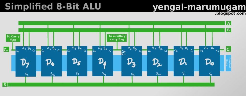
An 8-bit ALU is nothing but the series of ALU Slices cascaded one after another. The figure on the right shows the block diagram representation for the One-bit slice. This is to help the interpretation of following 8-Bit ALU.
Coming Up Next:
Consider any process has to be controlled. Who is to control? CPU is the controlling element of any process. This word appeared for the first time during 1960's in the Industries. In late 1960's microprocessor based CPU's came to rule the industries. The microprocessors require many external components for their operation. This increased the cost of project. So, the manufacturers came up with an idea of integrating the minimal external components inside it, necessary for its operation. As the area of application varies the manufacturer introduced a new device, that has many of the important accessories required by wide range of applications. Its is how our micro-controllers were born.
Microcontroller:
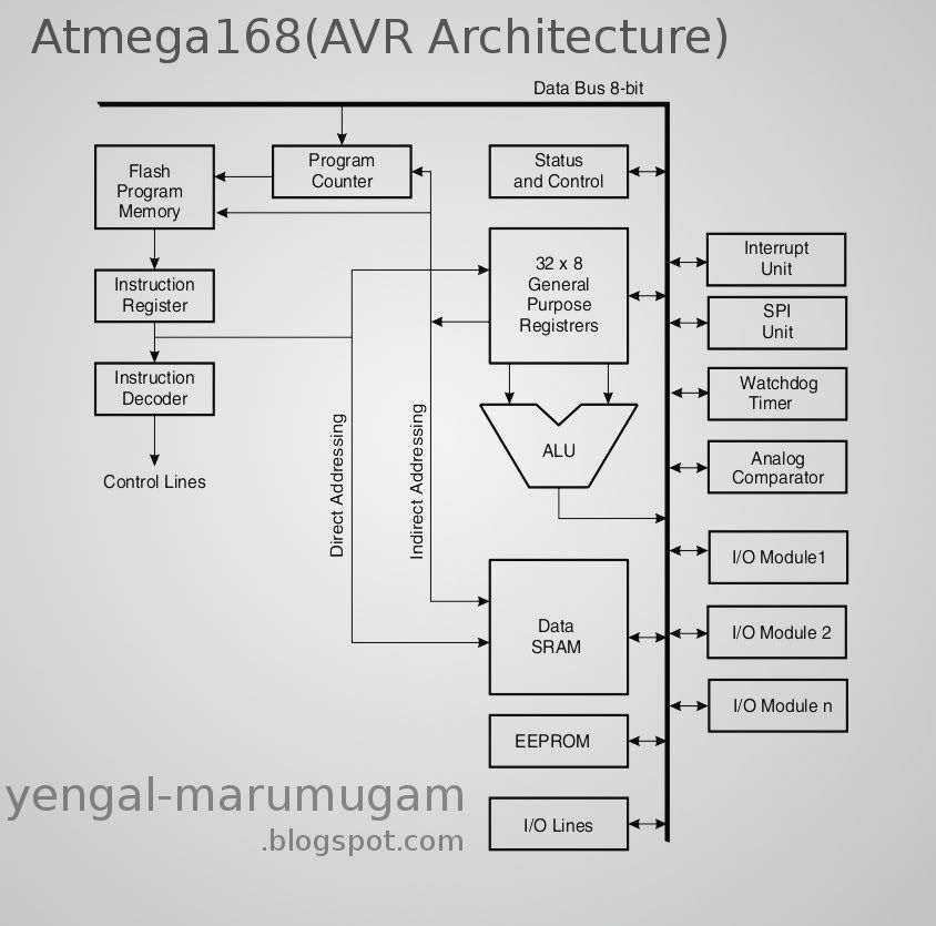
Micro-controllers = Microprocessor + Memory + AccessoriesThe following figure is of Atmega168 architecture.
CPU is the master of the microcontroller. Every CPU consists of Control Unit(CU) and Arithmetic Logic Unit(ALU).
Arithmetic Logic Unit: It performs Addition and Logical Operations like ANDing ORing. They when coupled with inverters, it can perform Subtraction, NANDing, NORing etc. You may have studied about the Adder circuits in Digital electronics. They are One bit adders. Four one bit adders combined to form four bit adder, i.e it could add two four bit numbers at a time. Similarly a 32-bit ALU can manipulate 32-bit numbers in one instruction cycle.
Control Unit: It has several important jobs to perform namely, instruction decoding, memory access, etc.. It activates the components of ALU and other parts of CPU. This is done by passing the specific control code to the components. A most simple Control Unit is a look-up table whose elements are indexed by the opcodes. i.e for every opcode, there is an equivalent control code.
e.g: for the instruction ADD B(add the contents of register 'B' with the contents of Accumulator and stores the results in Accumulator), there will be s series of control codes to activate the adder circuit and pass the operands to the adder, and to activate circuitry to store the result in the Accumulator.
Advanced Control Units are designed as Finite State Machines. They work based on the current state they present. It out of scope of this article.
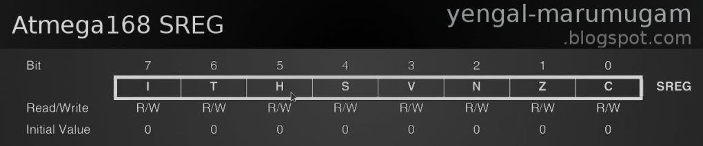
Other that ALU and CU, CPU consists of Register Bank/File, Status Register, Stack pointer. It is a series of 8-bit registers in 8-bit uC and 16-bit registers in 16-bit uC. These are called general purpose registers. Atmega168 contains 32x8-bit registers. 8085 CPU contains 6x8-bit registers. Status register has 8-bits of information about the previous arithmetic-logic operation.
| Bit | Symbol | Full name | Description |
| 0 |
C
| Carry Flag | The Carry Flag C indicates a carry in an arithmetic or logic operation. |
| 1 |
Z
| Zero Flag | The Zero Flag Z indicates a zero result in an arithmetic or logic operation |
| 2 |
N
| Negative Flag | The Negative Flag N indicates a negative result in an arithmetic or logic operation |
| 3 |
V
| Two’s Complement Overflow Flag | The Two’s Complement Overflow Flag V supports two’s complement arithmetics |
| 4 |
S
| Sign Bit | The S-bit is always an exclusive or between the negative flag N and the two’s complement overflow flag V |
| 5 |
H
| Half Carry Flag | The Half Carry Flag H indicates a half carry in some arithmetic operations. Half Carry is useful in BCD arithmetic |
| 6 |
T
| Bit Copy Storage | The Bit Copy instructions BLD (Bit LoaD) and BST (Bit STore) use the T-bit as source or destination for the operated bit. A bit from a register in the Register file can be copied into T by the BST instruction, and a bit in T can be copied into a bit in a register in the Register file by the BLD instruction |
| 7 |
I
| Global Interrupt Enable | The Global Interrupt Enable bit must be set for the interrupts to be enabled. The individual interrupt enable control is then performed in separate control registers. If the Global Interrupt Enable Register is cleared, none of the interrupts are enabled independent of the individual interrupt enable settings |
8-Bit ALU:The figure on the left shows the circuit for one bit operation. It is called One-bit Slice.
The ALU consists of different section for different operations. These section can be enabled with proper control codes(lines).
An 8-bit ALU is nothing but the series of ALU Slices cascaded one after another. The figure on the right shows the block diagram representation for the One-bit slice. This is to help the interpretation of following 8-Bit ALU.
Coming Up Next:
* AVR Instruction Set


3 comments:
Thats really helpful. I searched all over the internet for this. I found nothing... atlast here it is....
gud one..
Hello mate nicce post
Post a Comment
தங்களது கருத்துக்களை இங்கே வெளியிடவும்...