Showing posts with label Vanangamudi. Show all posts

Friday, 3 February 2012

Power Loss Indication

    Actually this stuff is made for a Simple(labs) competition. Problem statement is to indicate the power loss by blinking an LED after the power goes off. We thought of storing the charge in capacitor, like everyone. It seem simple at first, complex then, finally pretty easy.

    Operation is simple. When power is available the Capacitor is charged through the PN Junction Diode(1N4007). The transistor is kept ON by the power supply. When the power goes OFF, the Capacitor drives the 555 timer - Blinking Circuitry to indicate that the power is lost. Click here to see 555 timer Basics

Here is the circuit.

Operation Simplified....

   Actually the 555 timer circuitry operates in Astable Mutlivibrator Mode to generate a pulse. The pulse is used to drive the LED - On/Off. The supply to the 555 is supplied by the Charge Retention Capacitor (array). It is nothing but a ordinary capacitor of high capacitance value. Diode is used to prevent the transistor to be biased from capacitor. The transistor goes Off with the power, so the charge from Capacitor is used to run 555 timer circuitry.


Downloads:  Files    Video

Sunday, 23 October 2011

CPU Basics

     I was on hunting of resources on fundamentals of CPU. Energy exhausted. Everything  I found was incomplete, irrelevant. Yeah, Internet gives us clues to solve a puzzle. I think I almost solved it.

     Consider any process has to be controlled. Who is to control? CPU is the controlling element of any process. This word appeared for the first time during 1960's in the Industries. In late 1960's microprocessor based CPU's came to rule the industries. The microprocessors require many external components for their operation. This increased the cost of project. So, the manufacturers came up with an idea of integrating the minimal external components inside it, necessary for its operation. As the area of application varies the manufacturer introduced a new device, that has many of the important accessories required by wide range of applications. Its is how our micro-controllers were born.

Microcontroller:
   Micro-controllers = Microprocessor + Memory + Accessories 
The following figure is of Atmega168 architecture.


      CPU is the master of the microcontroller. Every CPU consists of Control Unit(CU) and Arithmetic Logic Unit(ALU).

     Arithmetic Logic Unit: It performs Addition and Logical Operations like ANDing ORing. They when coupled with inverters, it can perform Subtraction, NANDing, NORing etc. You may have studied about the Adder circuits in Digital electronics. They are One bit adders. Four one bit adders combined to form four bit adder, i.e it could add two four bit numbers at a time. Similarly a 32-bit ALU can manipulate 32-bit numbers in one instruction cycle.

    Control Unit: It has several important jobs to perform namely, instruction decoding, memory access, etc.. It activates the components of ALU and other parts of CPU. This is done by passing the specific control code to the components. A most simple Control Unit is a look-up table whose elements are indexed by the opcodes. i.e for every opcode, there is an equivalent control code.

e.g: for the instruction ADD B(add the contents of register 'B' with the contents of Accumulator and stores the results in Accumulator), there will be s series of control codes to activate the adder circuit and pass the operands to the adder, and to activate circuitry to store the result in the Accumulator. 

     Advanced Control Units are designed as Finite State Machines. They work based on the current state they present. It out of scope of this article.

     Other that ALU and CU, CPU consists of Register Bank/File, Status Register, Stack pointer. It is a series of 8-bit registers in 8-bit uC and 16-bit registers in 16-bit uC. These are called general purpose registers. Atmega168 contains 32x8-bit registers. 8085 CPU contains 6x8-bit registers. Status register has 8-bits of information about the previous arithmetic-logic operation.


Bit Symbol Full name Description
0
C
Carry Flag The Carry Flag C indicates a carry in an arithmetic or logic operation.
1
Z
Zero Flag The Zero Flag Z indicates a zero result in an arithmetic or logic operation
2
N
Negative Flag The Negative Flag N indicates a negative result in an arithmetic or logic operation
3
V
Two’s Complement Overflow Flag The Two’s Complement Overflow Flag V supports two’s complement arithmetics
4
S
Sign Bit The S-bit is always an exclusive or between the negative flag N and the two’s complement overflow flag V
5
H
Half Carry Flag The Half Carry Flag H indicates a half carry in some arithmetic operations. Half Carry is
useful in BCD arithmetic
6
T
Bit Copy Storage The Bit Copy instructions BLD (Bit LoaD) and BST (Bit STore) use the T-bit as source or destination for the operated bit. A bit from a register in the Register file can be copied into T by the BST instruction, and a bit in T can be copied into a bit in a register in the Register file by the BLD instruction
7
I
Global Interrupt Enable The Global Interrupt Enable bit must be set for the interrupts to be enabled. The individual interrupt enable control is then performed in separate control registers. If the Global Interrupt Enable Register is cleared, none of the interrupts are enabled independent of the individual interrupt enable settings


8-Bit ALU:
    The figure on the left shows the circuit for one bit operation. It is called One-bit Slice.

    The ALU consists of different section for different operations. These section can be enabled with proper control codes(lines).

    An 8-bit ALU is nothing but the series of ALU Slices cascaded one after another. The figure on the right shows the block diagram representation for the One-bit slice. This is to help the interpretation of following 8-Bit ALU.


Coming Up Next:

* AVR Instruction Set

Basics of Burning

     Making a micro-controller to work is not a simple one. It consists of different processes, namely coding, compiling, burning(device programming), on the software side. On the hardware side it consists of providing a clock, proper supply voltage(refer datasheet). These are the compulsory requirements for a micro-controller to work.

       Coding and compiling can be easily understood, because there are many tutorials in the internet. Burning and last important step for operation of micro-controller. Burning is the process of writing the compiled program(hex data) into the program memory of micro-controller. 

      To understand how burning works it is necessary to understand the CPU basics.  Here is a simplified explanation for it.

     CPU is a logical circuitry that executes the instructions from the RAM. The program can be stored in any permanent (memory) storage device. The program can be loaded into RAM from the permanent memory, then the CPU interprets the instructions from the RAM and executes it.

     CPU can store the contents (the program) from the RAM in any other storage devices, the program storage device too. Here afterwards we call program storage will simply called program memory.

    From the above description,we are clear that, it is enough for us to load the program into the RAM. The micro-controllers have instruction to to feed the RAM with the input from serial or parallel ports. This how it is going to store the program from our computer into program memory.

(to be continued)

Tuesday, 20 September 2011

Monostable Multivibrator- 555 timer

             It is a electronic circuitry (more specifically a relaxation oscillator), that maintains a HIGH or LOW at the output terminal for a fixed period of time interval (determined by  resistor capacitor pair), when a trigger is being given at the input. Other name is One-shot multivibrator.

       What the name indicates, is that the output has only one stable state. When triggered it goes to unstable state, remains there for some time and get back to stable state.

        We'll construct the circuit first with OpAmp and then with 555-timer IC.

555 TIMER:
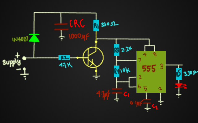
        The following circuit is the monostable multivibrator using 555-TIMER (IC NE555N). Briefly, the charging time of the circuit determines the time period of the output waveform.

555 Timer Block diagram and its Monostable Multivibrator Configuration.
     555 timer IC consists of a RS flip-flop whose Set and Reset terminals controlled by two comparators, and a three resistor potential divider network, which divides the supply voltage into three equal voltages . In case the supply voltage is 5V, it divided in three resistors as 1.667V. Therefore, the inverting terminal of the upper comparator is connected to 2Vcc/3 = 3.334V and the non-inverting terminal of lower comparator is connected to Vcc/3 = 1.667V. In addition 555 Timer IC also contains a NPN transistor. Its emitter terminal is grounded and collector terminal is called 'Discharge' to which we can connect external potential point that can be drained with the help of transistor. The transistor is operated by the RS flip-flop, since its base terminal is connected to the Q' terminal of RS flip-flop.

Monostable Multivibrator Operation:
     The circuit remains in stable state(LOGICAL-LOW for this circuit), as the current from the supply for RC pair is not allowed to charge the capacitor. At the time of start the, since the FLIPFLOP is reset, the Q' is HIGH(+5V). This drives the transistor into ON condition(saturation region). The functioning of the transistor is clearly understandable from the following figure:
     
   
How the Monostable multivibrator is driven into unstable state? 
  When the trigger is applied(i.e switch is closed), the 'Trigger' terminal (inerting terminal of lower comparator)  is directly connected to the ground(0V). This toggles the output of lower comparator from LOW to HIGH. So the SET terminal of FLIPFLOP is at HIGH, toggling the Q' to LOW. The output is HIGH.


How the Monostable multivibrator recovers from unstable state?
     As we have seen above the Q' is toggled from HIGH to LOW, which inturn turns-OFF the transistor. The capacitor(C) charges through Resistor(R). When the capacitor voltages just rises above the voltage at the inverting terminal of upper comparator, it toggles its output from LOW to HIGH. This resets the FLIPFLOP, i.e the Q' is again set to HIGH. Thus the transistor is driven into saturation and the cycle continues.

    When the trigger is given, the output is toggles for a finite time period determined by the time constant = RC.

The design formula derivation is shown below. The capacitor charging equation is used to derive the expression for On-time(unstable-state) for the output waveform. Vf is the voltage of the capacitor, if it is allowed to charge for infinite time period. It is equal to the given supply voltage. The figures on the right and below explain the derivation more elaborately.

   The main application of Monostable multivibrator is switch debouncing, where multiple pulses are generated for single press of the switch. It is also used for the conversion of frequency into proportional voltage. In my next post we will learn about the frequency to voltage(F/V) conversion.


Coming up next:
* Frequency to Voltage Conversion
* Application: Switch Debouncing
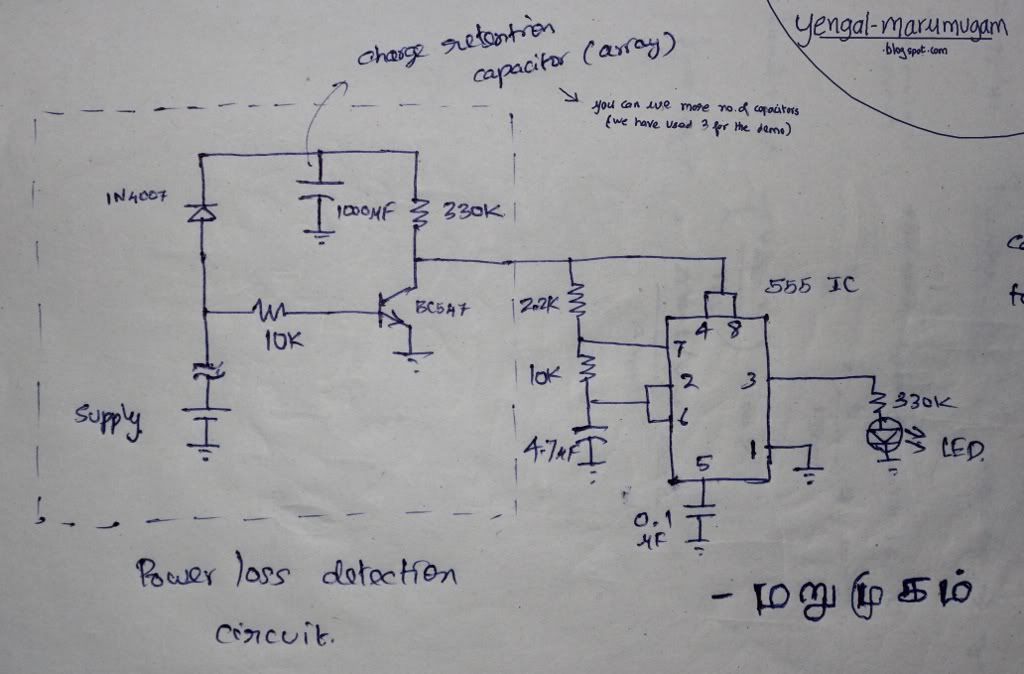


Sunday, 17 July 2011

Serial Port Manipulation in C

          Serial communications is the most popular and cheaper way of communicating between two devices. The obvious advantage is lesser number of conductors used. There are lots of information available in internet, so we'll focus on our experiment without discussing the in-depth details.

Serial Interface
         For communication between two or more devices there should be some well defined interface. In the world of Serial Communication it is specified by RS232. RS232 is defined by Electronic Industries Association (EIA). It defines the conventions to be followed for serial communication. At first, it is used for connecting telephone lines to the computer.  RS232-standard specifies the voltage levels for MARK (HIGH) and SPACE (LOW).

 Value            Voltage-range
 MARK         < -3V 
 SPACE        > +3V

Voltages between -3V and +3V is neither MARK nor SPACE
Female DB-9 RS232 Connector

Male DB-9 RS232 Connector


            In this experiment we are going to use only two pins namely TXD and SGND. We connect the TXD pin to Anode of LED and the Cathode of LED is connected to SGND through a Resistor. Thats all about the circuit. The DB-9 RS232 male connector is used to connect the circuit to the PC.

Pin
Symbol
I/O
Active HIGH/LOW
Description
Used/Not
1
DCD
Input
LOW
Data Carrier Detect
Not Used
2
RXD
Input
DATA
Receive
Not Used
3
TXD
Output
DATA
Transmit
Used
4
DTR
Output
LOW
Data Terminal Ready
Not Used
5
SGND
-
GND
Signal Ground
Used
6
DSR
Output
LOW
Data Set Ready
Not Used
7
RTS
Input
LOW
Request To Send
Not Used
8
CTS
Input
LOW
Clear To Send
Not Used
9
RI
Output
-
Ring Indicator
Not Used


Asynchronous Communication

               For the computer to understand the serial data coming into it, it needs some way to determine where one character ends and the next begins. This guide deals exclusively with asynchronous serial data.


              In asynchronous mode the serial data line stays in the MARK (HIGH) state until a character is transmitted. A start bit preceeds each character and is followed immediately by each bit in the character, an optional parity bit, and one or more stop bits. The start bit is always a SPACE (LOW) and tells the computer that new serial data is available. Data can be sent or received at any time, thus the name asynchronous.

             With these hardware background now we are going to dive into software part. I'm using Ubuntu Linux-10.10 ( Maverick Meerkat ). Linux already has serial port drivers. For now we'll see how to use those drivers. I'll discuss how serial drivers works in a separate article.

             In Unix/Linux everything is file. Yes, the serial port is also treated as file. So we can write and read the data to/from serial port just like a file.

The file names are as follows:
System Port-1 Port-2
Digital UNIX /dev/tty01 /dev/tty02
HP-UX /dev/tty1p0 /dev/tty2p0
IRIX /dev/ttyf1 /dev/ttyf2
Linux /dev/ttyS0 /dev/ttyS1
Solaris /dev/ttya /devttyb


Coding:

#include <stdio.h>     // Standard input/output definitions
#include <string.h>    // String function definitions
#include <unistd.h>   // UNIX standard function definitions
#include <fcntl.h>      // File control definitions
#include <errno.h>     // Error number definitions
#include <termios.h>  // POSIX terminal control definitions

// function to open the port
int open_port(void)
{
          int port;
          //open the port and store the file descriptor in 'port'
          port = open("/dev/ttyS0", O_RDWR | O_NOCTTY | O_NDELAY);
          if (port == -1){
                 // Could not open the port
                perror("open_port: Unable to open /dev/ttyS0 - ");
          }else{
                fcntl(port, F_SETFL, 0); //leave this
          }
          return (port);
}


int main()
{
          int port,n;
          char str[30];
          
          //termios - structure contains options for port manipulation
          struct termios specs; // for setting baud rate

          //setup part
          port = open_port();
          tcgetattr(port, &specs);

          //now the specs points to the opened port's specifications
          specs.c_cflag = (CLOCAL | CREAD ); //control flags


          //output flags
          //CR3 - delay of 150ms after transmitting every line
          specs.c_oflag = (OPOST | CR3);


         //set Baud Rate to 50bps
         cfsetospeed(&specs,B50);


         //our custom specifications set to the port
         //TCSANOW - constant that prompts the system to set
         //specifications immediately.
          tcsetattr(port,TCSANOW,&specs);
         
          //execution part
         printf("\nEnter the data:\t");
         scanf("%s",str);
         n = write(port,str,11); // n = no of bytes written
         if (n<0) {
              printf("\nError");
         }


         //close the port
         close(port);
         return(0);


Here is mine. It is no a good practice to solder individual wore. Set of six wire sleeves are available in shops. Use them.


Connect the  the Serial Cable to your PC and execute the program. Happy Blinking!!!

Share

Twitter Delicious Facebook Digg Stumbleupon Favorites More